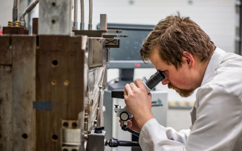
What is plastic injection molding?
Plastic injection molding is like a magic trick for making all sorts of plastic things. It works by melting plastic, putting it into a mold, and then cooling it to make everything from toys to machine parts.
What are some common plastic injection molding problems?
Plastic injection molding can encounter various issues that affect product quality, aesthetics, and efficiency. These problems range from surface defects like burn marks and streaks to structural issues like warpage and brittleness.
Why is it important to avoid plastic injection molding problems?
Sometimes, the magic doesn’t work perfectly. The plastic can come out wrong, causing problems. These problems can make things look bad, work poorly, and even cost more to fix. That’s why it’s crucial to know how to prevent these problems.
Material Handling and Contamination
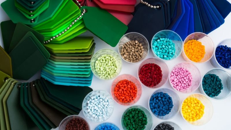
Think of making plastic stuff like baking a cake. If you use bad eggs or flour, the cake won’t taste right. In plastic molding, the material we start with must be clean and perfect. If it’s not, we get bad plastic parts.
Material Cleanliness
Ensuring the cleanliness of the plastic resin is paramount. Even minute traces of foreign substances, such as dust, moisture, or contaminants, can lead to defects like voids, streaks, or even structural weaknesses in the finished product.
Material Handling Best Practices
Proper material handling is the foundation of defect prevention. Manufacturers should establish and adhere to rigorous procedures for material storage, transportation, and loading. Here are some key best practices:
- Storage Conditions: Raw plastic material should be stored in a controlled environment with temperature and humidity conditions that align with the material’s specifications. This prevents moisture absorption and material degradation.
- Material Inspection: Regularly inspect incoming material shipments for signs of damage or contamination. Reject any material that doesn’t meet quality standards.
- Drying and Preconditioning: Many plastic resins are hygroscopic, meaning they absorb moisture from the air. Drying and preconditioning are essential steps before processing to remove any absorbed moisture.
- Clean Handling: Operators must wear gloves and use clean tools when handling material. Avoiding contact with bare hands helps prevent contamination.
- Clean Equipment: Ensure that all equipment, including hoppers and conveyors, is clean and free from debris before introducing material.
- Dust Control: Implement dust control measures in the manufacturing environment to minimize the risk of airborne contaminants settling on the material.
Prevention and Detection
Detecting material contamination before it enters the injection molding machine is crucial. Modern technology, such as inline inspection systems and advanced sensors, can help identify inconsistencies in material quality in real-time, allowing for swift corrective action. Click to learn how to choose plastic material.
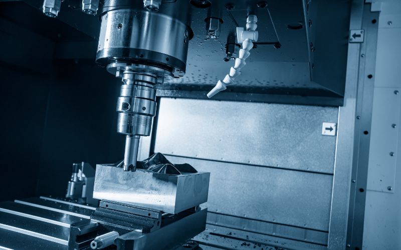
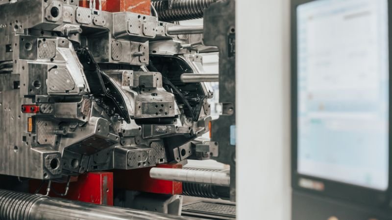
Mold Design and Venting
The heart of any successful plastic injection molding process lies in the mold itself. A well-designed mold not only dictates the final product’s form but also plays a crucial role in preventing defects. Mold design encompasses various elements, from cavity structure and gate placement to venting solutions, all of which directly impact the quality of the finished parts.
Air Traps
Air traps, or trapped air pockets within the mold cavity, are a common issue that can result in undesirable defects such as voids, burns, and poor surface finish. These pesky air traps occur when air gets trapped during the injection process, preventing the molten plastic from filling the cavity completely.
The Role of Mold Venting
Effective mold venting is the key to preventing air traps. Venting involves providing pathways for trapped air to escape from the mold cavity as the molten plastic is injected. Proper venting allows for uniform filling of the mold and ensures that air doesn’t become entrapped, leading to defects.
- Vent Design: Engineers meticulously design vents into the mold to facilitate the release of air without compromising the integrity of the final product. These vents are typically narrow and strategically placed in areas where air is likely to become trapped.
- Venting Material: Venting material must be carefully selected to withstand the abrasive nature of the plastic resin and to resist wear and tear over time.
- Maintenance: Regular mold maintenance is essential to keep vents clean and free from obstructions. Over time, contaminants or plastic residue can accumulate in vents, hindering their effectiveness.
Mold Corrosion
Mold corrosion is another challenge that can affect the quality of injection-molded products. Corrosion occurs when the mold material deteriorates due to various factors, including the aggressive nature of some plastic resins, moisture, and temperature fluctuations.
Strategies for Mold Corrosion Prevention
Preventing mold corrosion requires a proactive approach:
- Mold Material Selection: Choose mold materials that are corrosion-resistant and suitable for the specific plastic resin being processed. Stainless steel and corrosion-resistant coatings are viable options.
- Vent Maintenance: Regularly inspect and maintain vents to prevent corrosion. Cleaning and applying protective coatings can prolong the life of the vents.
- Environmental Control: Maintain the manufacturing environment within specified temperature and humidity ranges to reduce the likelihood of mold corrosion. It’s essential for both the longevity of the mold and the quality of the final product.
- Surface Treatments: Applying specialized coatings or surface treatments can help protect the mold from corrosion.
- Proactive Maintenance: Implement a proactive mold maintenance program that includes routine cleaning and inspection to detect and address corrosion issues before they escalate.
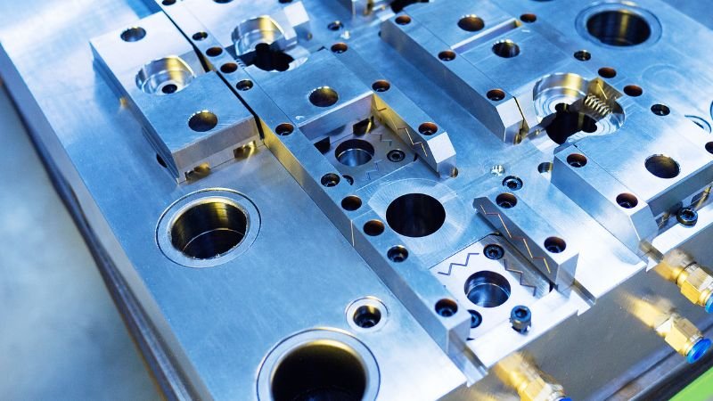
Mold Gate Placement
Gate placement is another crucial aspect of mold design that can significantly impact the quality of injection-molded parts. The gate is the entry point through which molten plastic enters the mold cavity. Proper gate placement is essential for ensuring uniform filling, minimizing defects, and achieving the desired part properties.
Gate Types and Selection
Different types of gates are available, each with its own advantages and limitations. The choice of gate type depends on various factors, including part design, material, and production volume. Common gate types include:
- Direct Sprue Gate: Located directly at the sprue, this gate type provides a straightforward path for material flow. It’s often used for large parts.
- Submarine Gate: This gate type is located beneath the part’s surface, making it less visible in the finished product.
- Edge Gate: Positioned at the edge of the part, this gate type is suitable for parts with complex geometries.
- Hot Runner System: In a hot runner system, molten plastic is maintained at an elevated temperature, allowing for multiple gates without the need for runners. This minimizes material waste and is often used in high-volume production.
Gate Size and Geometry
The size and geometry of the gate also play a critical role in the injection molding process. A gate that is too small can restrict material flow and lead to filling issues, while an oversized gate may result in excessive material usage and cosmetic defects.
- Gate Size Optimization: Engineers carefully calculate and optimize gate size based on factors such as material properties, part design, and production requirements.
- Gate Geometry: The shape of the gate affects material flow and shear stress. Rounded or tapered gates are often preferred to minimize stress concentrations and cosmetic defects.
The Art of Multiple Gates
In some cases, using multiple gates can enhance the injection molding process. Multiple gates are strategically placed to achieve even material distribution, reduce the risk of flow lines or weld lines, and ensure uniform packing of the mold cavity.
- Balanced Flow: Multiple gates allow for balanced material flow into the mold, reducing the risk of uneven filling and defects.
- Improved Cosmetic Appearance: Multiple gates can minimize the appearance of gate marks on the finished product, enhancing its cosmetic appeal.
- Enhanced Structural Integrity: Uniform filling and packing, facilitated by multiple gates, contribute to improved part strength and structural integrity.
Mold Temperature Control
Mold temperature control is a critical factor in plastic injection molding that can significantly impact part quality, aesthetics, and performance. Maintaining consistent and uniform mold temperatures throughout the production process is essential to prevent defects like warpage, sink marks, and dimension inaccuracies.
The Importance of Mold Temperature
Mold temperature affects various aspects of the injection molding process:
- Material Flow: Proper mold temperature ensures that the molten plastic flows smoothly into the mold cavity, minimizing defects.
- Cooling: Uniform mold temperature is essential for even and efficient cooling of the part, preventing warpage and other issues.
- Cycle Time: Optimizing mold temperature can lead to reduced cycle times, increasing production efficiency.
Achieving Uniform Mold Temperatures
Maintaining consistent mold temperatures requires careful control and monitoring. Here are some strategies to achieve uniform mold temperatures:
- Cooling Channels: Well-designed cooling channels in the mold help distribute coolant evenly, preventing hot spots or cold areas.
- Coolant Type and Flow Rate: The choice of coolant and its flow rate are critical factors. Coolants with excellent heat transfer properties and optimized flow patterns are preferred.
- Temperature Control Systems: Implementing advanced temperature control systems allows for precise regulation of mold temperatures. This ensures that the mold remains within a narrow temperature range during production.
- Addressing Mold Temperature Variation: Temperature variation within the mold can lead to uneven cooling and, consequently, defects. Regular mold maintenance and adjustments are essential to counter temperature variations.
Check PMS Mold Tooling Service
As we move further along the plastic injection molding process, we arrive at the injection phase, which is the juncture where molten plastic material is introduced into the mold cavity.
Short Shots: When Fillings Fall Short
Short shots occur when the mold cavity isn’t completely filled during the injection phase. This leads to incomplete or undersized parts, which can be a significant issue, particularly when precision and consistency are paramount.
Causes of Short Shots
Short shots can be caused by a variety of factors, including:
- Insufficient Material: Inadequate material volume can result in a short shot. This might occur due to errors in material calculations or a malfunction in the injection unit.
- Mold Design: Improper mold design, including gate size and location, can restrict the flow of plastic and lead to incomplete fillings.
- Temperature and Pressure: Inaccurate temperature or pressure settings can hinder the material’s ability to flow into all areas of the mold.
Remedies for Short Shots
Addressing short shots requires careful consideration of several factors:
- Material Volume Adjustment: Ensure that the correct amount of material is injected into the mold by calibrating and verifying the injection unit’s settings.
- Mold Design Review: Regularly review and optimize mold designs to ensure that gate size and location facilitate complete cavity filling.
- Temperature and Pressure Control: Precisely control temperature and pressure settings to promote material flow into all parts of the mold.
Overpacking: The Pitfall of Excess
While short shots leave parts underfilled, overpacking involves injecting an excessive amount of material into the mold. This can result in defects like warpage, flash, or even damage to the mold itself.
Causes of Overpacking
Overpacking can occur due to:
- Excessive Injection Speed: Injecting material too quickly can lead to overpacking as the molten plastic encounters resistance in the mold.
- High Pressure: Elevated injection pressure can cause the material to pack too tightly within the mold, leading to overpacking.
Achieving Injection Precision
Balancing the need for complete cavity filling with the avoidance of overpacking requires precise control and monitoring. Manufacturers must focus on:
- Injection Speed: Adjust the injection speed to ensure that the mold cavity is adequately filled without the risk of overpacking.
- Pressure Control: Implement pressure control systems that maintain optimal pressure levels throughout the injection process.
- Material Flow Analysis: Utilize software and analysis tools to simulate material flow within the mold, identifying potential issues before production.
- Mold Design Review: Regularly review mold designs to ensure that gate size and location facilitate complete filling without overpacking.
Learn PMS Injection Molding Process
As we progress through the stages of plastic injection molding, we reach the ejection phase, where the final product is released from the mold. This seemingly straightforward step presents its own unique challenges that can affect the quality and appearance of the finished part.
Ejector Pin Marks
Ejector pin marks are common imperfections that can mar the surface of an otherwise flawless product. These marks occur when the ejector pins, which are used to push the product out of the mold, leave behind small indents or blemishes.
Causes of Ejector Pin Marks
Ejector pin marks can be attributed to various factors, including:
- Ejector Pin Design: Inadequate design, such as the use of overly large or small pins, can result in noticeable marks on the product surface.
- Ejector Pin Positioning: Poorly positioned ejector pins can cause marks in conspicuous areas, affecting the product’s aesthetics.
- Injection Speed: High injection speeds can increase the force with which ejector pins push parts out of the mold, leading to marks.
Mold Filling Imbalances
Mold filling imbalances occur when the molten plastic material doesn’t flow evenly throughout the mold cavity, resulting in parts with inconsistencies in thickness and properties.
Causes of Mold Filling Imbalances
Several factors can contribute to mold filling imbalances, including:
- Inadequate Gate Design: Gates that are too small or improperly positioned can hinder the even flow of plastic material.
- Temperature Variations: Uneven mold temperatures can affect material flow, leading to filling imbalances.
- Material Viscosity: Variations in material viscosity can result in uneven filling.
Remedies for Ejector Pin Marks and Filling Imbalances
Addressing these issues requires a combination of careful design, precise control, and maintenance practices:
- Ejector Pin Design Review: Regularly review ejector pin design to ensure appropriate size and positioning. Consider the use of multiple pins to distribute the force evenly.
- Gate Optimization: Optimize gate design for even material flow. Proper gate location and size can significantly reduce filling imbalances.
- Temperature Control: Maintain uniform mold temperatures to ensure consistent material flow.
- Material Selection: Choose materials with consistent viscosity properties to reduce the risk of filling imbalances.
Cycle Time
Cycle time optimization is an essential aspect of post-injection considerations. It refers to the effort to reduce the time it takes to complete each cycle of the injection molding process, from material injection to part ejection.
Factors Affecting Cycle Time
Several factors influence cycle time, including:
- Injection Speed: Adjusting the injection speed can impact cycle time. Faster injection speeds may reduce the time required for filling the mold but can introduce other issues.
- Cooling Time: Cooling time is a significant contributor to cycle time. Optimizing cooling strategies can help reduce overall cycle times.
- Ejection Process: Efficient ejection mechanisms can help minimize the time spent removing parts from the mold.
Warpage
Warpage is a persistent challenge in plastic injection molding, and it can occur at various stages of the process. Warpage involves the deformation or distortion of the molded part, resulting in deviations from the intended shape or dimensions.
Causes of Warpage
Warpage can be caused by several factors:
- Uneven Cooling: Variations in cooling rates can lead to differential shrinkage and warpage.
- Material Selection: The choice of material plays a significant role in warpage. Some materials are more prone to warpage than others.
- Part Design: Poor part design, including excessive wall thickness variations, can increase the risk of warpage.
Strategies for Warpage Prevention and Mitigation
Addressing warpage requires a multifaceted approach:
- Cooling Strategy: Optimize cooling strategies to minimize differential cooling and reduce the risk of warpage.
- Material Selection: Carefully select materials that are less prone to warpage for specific applications.
- Part Design Review: Continuously review part designs to identify potential sources of warpage and implement design improvements.
We encounter a fresh set of issues that demand our attention. These issues include fog, sink marks, weld lines, and the elusive problem of streaks.
Burn Marks: The Scars of Overheating
Burn marks, also known as “witness marks” or “blisters,” are unsightly discolored areas on the surface of molded parts. They often appear near the gate or on the thicker sections of the part and are the result of localized overheating during the injection process.
Causes of Burn Marks
Burn marks can be attributed to several factors:
- Excessive Injection Speed: Rapid injection of molten plastic can generate excessive heat, leading to burn marks.
- Inadequate Cooling: Insufficient cooling can allow heat to accumulate in localized areas, causing burn marks.
- Material Resin Degradation: Some plastic resins are more prone to thermal degradation, leading to burn marks.
Delamination: The Layered Dilemma
Delamination refers to the separation of layers within a molded part. It typically manifests as visible lines or separations, compromising both structural integrity and aesthetics.
Causes of Delamination
Delamination can occur due to:
- Inadequate Material Mixing: Poor blending of materials during the molding process can result in delamination.
- Material Contamination: Contaminants introduced during material handling or processing can cause layers to separate.
- Inadequate Melt Temperature: Incorrect melt temperature settings can contribute to delamination.
Jetting: The Speed Dilemma
Jetting is a phenomenon where a high-speed stream of molten plastic material impacts the mold surface, creating visible streaks or lines on the finished part. It’s often associated with the use of high-viscosity materials.
Causes of Jetting
Jetting can be triggered by:
- High Injection Speed: Excessive injection speeds can lead to jetting, as the material impacts the mold surface rather than flowing smoothly into cavities.
- Gate Design: Improper gate design can exacerbate jetting issues.
Flow Lines: The Path of Least Resistance
Flow lines, also known as “weld lines” or “knit lines,” are often visible as faint lines or ridges on the surface of a part. They occur when the flow of molten plastic material encounters resistance and rejoins, leaving a visible seam.
Causes of Flow Lines
Flow lines can result from:
- Material Cooling: Variations in cooling rates can cause material to solidify at different times, leading to flow lines.
- Complex Part Geometry: Parts with complex geometries or multiple branches are more susceptible to flow lines.
Strategies for Defect Mitigation
Mitigating these defects requires a combination of design, process optimization, and material selection:
- Gate Redesign: Proper gate design and placement can reduce the risk of burn marks, delamination, and jetting.
- Optimized Injection Speed: Control injection speeds to prevent overheating and jetting while ensuring proper material flow.
- Material Selection: Choose materials that are less prone to burn marks and delamination.
- Tooling and Mold Design: Implement tooling changes and mold design improvements to reduce the likelihood of flow lines.
Fog: The Haze of Imperfection
Fog, often referred to as “hazing” or “misting,” appears as a cloudy or hazy surface on the molded part. This defect can significantly affect the product’s aesthetics and clarity.
Causes of Fog
Fog can occur due to:
- Material Contamination: Contaminants introduced during material handling or processing can lead to fog.
- Overheating: Excessive temperatures during the molding process can cause the material to degrade, resulting in fog.
Sink Marks: The Indentation Challenge
Sink marks are depressions or indentations on the surface of a molded part. They occur when the surface of a thicker section of the part cools and solidifies more slowly than the inner areas.
Causes of Sink Marks
Sink marks can be caused by:
- Inadequate Cooling: Uneven cooling, especially in thicker sections of the part, can lead to sink marks.
- Material Shrinkage: Differential shrinkage rates within the part can result in sink marks.
Weld Lines: Where Materials Meet
Weld lines, also known as “knit lines,” occur when two or more molten plastic flow fronts meet and rejoin during the injection process. These lines are often visible on the surface of the finished part and can affect its structural integrity.
Causes of Weld Lines
Weld lines can form due to:
- Material Flow Restrictions: Obstacles or geometry within the mold can cause material flow to split and rejoin.
- Material Cooling: Variations in cooling rates can lead to the formation of weld lines.
Streaks: The Unsightly Marks
Streaks, as their name suggests, are visible lines or streaks on the surface of a molded part. They can be caused by a variety of factors and are often challenging to diagnose and resolve.
Causes of Streaks
Streaks can result from:
- Material Contamination: Contaminants or impurities in the material can cause streaks.
- Inadequate Mixing: Poor mixing of materials can lead to streak formation.
Strategies for Defect Resolution
Resolving these challenges demands a combination of design, process optimization, and material management:
- Material Purity: Ensure that the material used is free from contaminants and impurities.
- Cooling Optimization: Optimize cooling strategies to reduce the risk of sink marks and fog.
- Mold Design Review: Continuously review mold designs to identify potential sources of weld lines and streaks.
- Material Selection: Carefully select materials that are less prone to streak formation and other defects.
Learn how PMS control quality.